
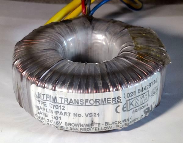
Wiring Antrim ® Toroidal Mains Transformers
There seems to be an absence of this information on the internet, although I have noticed that Antrim ® have put up some details themselves when I got around to writing this page, which was originally here. However, this link seems to not work anymore, and it appears that Antrim were acquired by Trans-Tronic Ltd.
For those who are a bit worried about wiring a toroidal transformer for the first time (I know I was), this article should help you become more confident in how you are wiring the transformer into your system. For the example, I will be showing you how I've wired up various toroidal transformers, such as those used my amplifiers.
This article used to be specific to Antrim ® toroidal transformers only, but I have expanded it to cover a range of RS, Vigortronix, Multicomp and others. Information here though should be applicable to all toroidal transformers - just pay attention to the colouring of the wiring and match it to the label.
WARNING:
WIRING TRANSFORMERS MEANS MAINS VOLTAGES ARE INVOLVED. YOU SHOULD NOT DO THIS UNLESS YOU ARE QUALIFIED TO DO SO AND VERY CAREFUL ABOUT YOUR WORK.
Firstly, let's have a look at what wires toroidal transformers usually have. There are four wires for the primary windings, and another four for the secondary windings. This allows both parallel and series windings. I will explain this a bit more later, but first we shall look at the primary windings.
The primary windings on these transformers are where the mains voltage connects. This is very critical, and things must be correct, or consequences will be fatal. The diagrams below are a repeat of the Antrim ® page linked above, for the convenience of printing and reminding you how to wire these transformers.
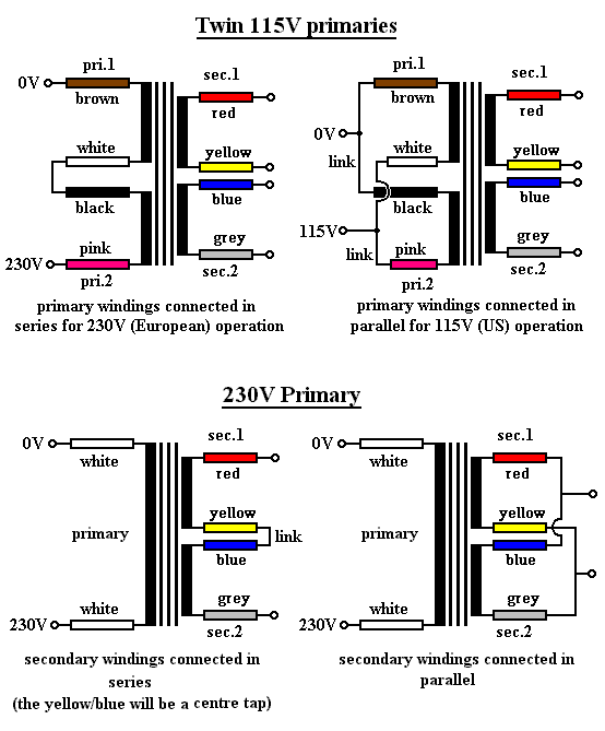
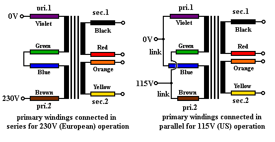
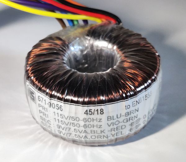
This diagram below refers to the colour scheme used on more recent RS Pro transformers:
And this diagram below refers to the colour scheme that I've more commonly found on transformers:
The transformers you will be likely to obtain will be the twin 115V primary winding versions. You will be one of the two following situations:
- You are a European or elsewhere in the world where your mains voltage will be 220V to 250V AC.
- You are American, Canadian, Japanese, and you have 100V to 120V AC mains voltages
If you don't know what voltage your country is using, you shouldn't be at this stage of electronics just yet ;-)
A NOTE ON CUTTING THE WIRES:
I have commonly found that once wires are shortened, and the insulation cut back for soldering that there was a protective (enamel) layer over the
copper core. This layer cannot be burnt off by a 25W soldering iron and you need to remove it by other means. What I did was to get a needle file
and file very carefully the edges of the copper core. This needs to be done very mildly indeed and overdoing it means that you will thin the wire
too much which can cause it to break in time or provide too much resistance. Remember, mains voltages will be traveling in these wires.
Another (and perhaps better) alternative of removing the coating is to use a Stanley/modelling knife (or similar). Small disposable knives are the easiest to use. Usual rules apply when doing this, scrape the coating off in a direction away from your fingers (or anyone else's) to avoid injury if you slip. Also, don't do this on your best table ;-) and never leave the knife around once you have finished. Some transformers come with the wires ready for you - so unless necessary, I wouldn't recommend shortening the wires at all for the sake of saving hassle of finding that they are coated.
For mains (the primary wires), soldering is less recommended than terminal blocks. If you do solder, make sure the joint and cable insulation near it is insulated again. Also make sure the mains cable is secured near the joint and has some strain relief - solder affects the flexibility of the cable and if it is allowed to move, then it may break more easily, touch the case and case the safety earth to trip (or worse if you forgot to connect that one!). Never solder the safety earth - make sure it is screwed to the case via multiple toothed washers and two nuts.
Wiring the Primary Windings
Let's look at the 220-250 AC voltages. These are the case in most of the world, including the UK, where I am based. If this is your case, you will need to wire your transformer in exactly the way described by the diagram in the top left above. That means you will be connecting the two primary coils in series.
Antrim - 220V to 250V Primary
In the first diagram (Antrim ®), connect the White and Black together. Then, very carefully insulate them, making sure they will never break free from the insulation now, or in many years' time!
You now have two wires left on the primary winding, which as you can see connect to your mains AC input. Rather than joining the wires to others, if you can, connect them straight to a mains input socket, via a fuse, and a switch. Again, if they are shortened, you will need to remove the protective layer. The Brown wire will connect to the neutral input, while the Pink wire will go to the Live (active) input.
Note that this is a bit confusing for Europeans to have the brown wire connected to neutral. You can do it the other way round (brown in live, pink in neutral) if you prefer, but I like to follow the standard of the 0V marked connection is neutral. This is usually the first listed colour on the transformer's label.
RS Pro (recent) - 220V to 250V Primary
This can be a little confusing at first, because the European standard mains wire colours (blue and brown) do not connect to the mains in this way.
To connect these transformers to 220-250V AC mains, connect the Green and Blue together. Carefully insulate them, making sure they will never break free from the insulation now, or in many years' time!
You now have two wires left on the primary winding, which as you can see connect to your mains AC input. The Violet wire will connect to the neutral input, while the Brown wire will go to the Live (active) input, via a fuse.
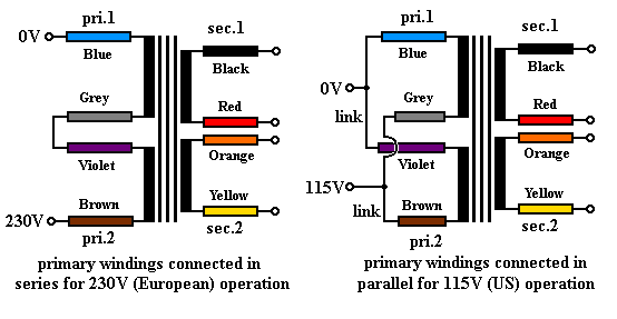
Others - 220V to 250V Primary
For others, connect Grey and Violet together.
You'll then be left with Blue, which connects to neutral, and Brown connects to Live, via a fuse. Quite often easy to remember for these ones as it is the colour scheme of the cable in non-Americas.
Antrim - 100V to 120V Primary
If you are an American, or other country with 100-120 AC mains voltage, you will need to wire the primary windings differently. You will need the parallel arrangement, as shown in the top right diagram above.
This means that you will connect together the White and Pink wires and connect them to the live output of your mains socket or switch, via a fuse. Standard live colour for US mains is Black. Both of these wires will need to be joined together, and the mains input too.
The other two wires of the primary coil on the transformer also connect together and run to the other side of the mains input. This means that Brown and Black will join and run to the neutral (White) coloured wire on the mains input. Careful connection and insulation are of course recommended.
Do not connect the primary windings in any other way, otherwise they will not be in phase and your transformer will not be happy about that! The phase is often marked with a single dot on the colour of the wire.
RS Pro (recent) - 100V to 120V Primary
For these transformers, connect both Blue and Violet together, then connect these to neutral (White).
The remaining Brown and Green wires connect together, and also connect to live AC input (Black), via a fuse.
Others - 100V to 120V Primary
Connect both Blue and Violet together and connect them to the 0V neutral.
Now connect both Grey and Brown, then connect them to the live 100 to 120VAC mains (via fuse).
Fuses and safety:
Don't forget that when wiring to the mains, it should be via a fuse on the Live/Active/Hot wire!
A fuse is there for safety, and it will prevent a fault (causing large current draw) and your project going up in flames!
Toroidal transformers have a large inrush current (a higher than normal current during power up). With a 500VA toroidal I have seen the lights in the house dim briefly when it is powered on.
This inrush current will blow fast acting fuses. This means you will need to use a Time Delay / Slow Blow fuse instead, typically indicated with a T (such as T1A - a 1 amp time delay fuse)
The fuse to use may be recommended by the manufacturer. If it is not, you will need to choose one that allows the current multiplied by your voltage to exceed about 150% of the VA rating of your transformer
For example, if you have a 500VA transformer, operating at 250V, divide 500VA by 250V. You get 2 amps. Multiply by 150% and the fuse is 3 amps.
A rating between 3 and 4 amps will be fine (3.15A is quite common). A 2 amp fuse will likely cause nuisance blowing because of inrush current and inefficiencies in the transformer.
For a smaller transformer, the same logic applies. For 40VA for example, 40 divided by 250V is 0.16. Multiplied by 150% (1.5) and you get 0.24. A 0.25A (T250mA) fuse is perfect.
Earthing: Your transformer will usually be put in metal case. Always Earth it by connecting to the safety earth of your mains input. This is typically the Green/Yellow wire.
You should also connect the earth to the ground on the secondary side of the transformer, allowing protection of the user touching the low voltage switches etc. in case the transformer was to develop a fault where the primary and secondary coils are shorted.
This can cause noise in audio (hum) or other equipment but connecting via a loop breaker will often solve that. See the PSU examples below that include the use of a diode bridge rectifier (BR2), a 10 ohm 5W resistor (R1) and a mains rated 100nF capacitor (C3) to form an effective loop breaker, without compromising safety. Here, R1 limits the current of earth loops, but DB1 will conduct fault currents, ensuring you are protected in case of a transformer fault. C1 helps ensure high frequency RF interference is still directly sent to earth/ground.
Make it a habit to think that whenever you power on your circuit after changing it or opening the box, before powering it up, check the safety earth is connected!
Mounting: Toroidal transformers usually come with a long bolt, nut and a disk for mounting in the case (sometimes with extra rubber disks). Be aware of a metal case that the top of the bolt does not touch the top of your case. Since this bolt is already touching the bottom, if it touches the top too then via the rest of the case will effectively make a shorted turn around the transformer core itself, and damage will result.
Wiring the Secondary windings
You have typically three types of desired output from your transformer:
- An AC output (such as powering light bulbs, motors)
- A single rail DC supply (contains a positive and ground, the most common type of DC supply)
- A split rail DC supply (contains a positive, negative and ground, typically used for audio applications)
For types 1 and 2, you will want to parallel the secondary wirings to get the most power output from the transformer.
Type 3, a split rail PSU, can make use of a centre tapped transformer. A centre tap can be easily obtained from these transformers which have dual secondary windings.
First, we will consider the AC / single supply scenario. This requires you to parallel the secondary wirings of the transformer. What you will get from this is a standard two wire AC output with no centre tap. For a 2x 12V transformer, you will get 12V AC output, but a current that is double the rating of each winding individually. To get this configuration correct, follow the diagram at the bottom right above.
It is very important that the phasing of the wiring is correct when connecting the secondary coils in parallel. The phase is usually marked by a dot - connect the secondary wires marked with a dot together, and the secondary wires without together and you get your two wire AC output.
For the Antrim ® example Blue and Red connect together and give you one side of the AC voltage. Yellow and Grey join to give you the other side of the AC voltage.
For other common transformers (including RS Pro transformers), Red and Yellow connect together and give you one side of the AC voltage. Black and Orange join to give you the other side of the AC voltage.
The first diagram above shows how this can be done - you need to look at the bottom right. The 2x 12V AC transformer is now a 1x 12V AC transformer with full current capability. The maximum current that can be pulled in this configuration is the total rated by the transformer (i.e., the rated current for each winding added together).
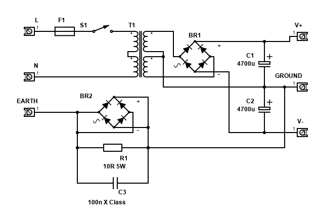
From this configuration, it can be easy to set up a single rail PSU as shown below, using a bridge rectifier (BR1) to change AC to DC, and capacitor C1 to smooth the DC ripple.
This example shows the dual primary in series for 230V+ operation, and dual secondaries in parallel for high current operation.

Note that BR2, R1 and C3 form an earth loop breaker (see above), which helps remove hum in amplifiers. If you do not need a loop breaker, please instead connect the ground (0V) directly to safety earth to ensure you are protected in all faults.
Next, we'll consider the secondary coils in series, giving us a centre tap.
For centre tapped - the first diagram above again shows how this can be done - you need to look at the bottom left. What you will get is a centre tapped wiring - the centre tap is where the word link is. In a 2x 12V transformer example, the configuration 12-0-12. The maximum current that can be pulled in this configuration is half that rated by the transformer (i.e., the rated current for each winding) as you are effectively getting two times the voltage.
With a centre tap, you can get a split rail PSU, like this one. This again shows the primary coils in series for 230V+ operation, but with the dual secondaries in series to get the centre tap:
With Antrim ® transformers, to get this wiring arrangement, you need to connect the Yellow and Blue wires together. This will give you the centre tap, or 0V, that can then be connected to ground typical circuit applications. The other two wires left will be the two AC voltages, in the case of a 12V transformer, it will be two 12V connections. This is obviously given by the Red and Grey wires and in most PSU applications, they will go to the AC inputs of the bridge rectifier (or diodes).
For an example of common transformers (including RS Pro), it is usually Red and Orange connected together to form the centre tap 0V. Black and Yellow are the two AC connections.
It is important to connect both secondary windings of the transformer in-phase. If your wire colours do not relate to those above, your transformer coil's phase can sometimes be identified with a dot, and very often the colours listed are in order anyway. The centre tap should be between the end of the first winding, and the start of the next.
Again, careful insulation and wiring is required as in some cases, these secondary windings will be of high voltage, i.e., a 2x 40V transformer could kill you, especially after it is converted to DC, which will give you over 110V DC!
If you cannot identify which cables are which, there are some tricks to help. Sometimes the wires on the primary are thinner (but not always!). This is because they carry a smaller current (but higher voltage), so the resistance is not as important.
You can then identify which wires form a coil by checking to see if they form a short circuit/continuity on a multimeter. If they do, then these two wires will be a coil. Check the resistance too - the primary coils should have a slightly higher resistance than the secondary coils (for step-down transformers).
If you have a dual secondary transformer though, identifying the phase is not easy without using an oscilloscope or similar equipment to measure the AC waveform, to see whether the phase in matches the phase out. Every dual secondary transformer I've come across usually has a dot or some indication though, and the colours are listed out in order on the label - for example BLK - RED for the first coil, ORN - YEL for the second coil. Black and Orange will be the same phase as they are listed first. Connecting out of phase might still appear to work when rectified to DC, but you'll get larger bursts of AC resulting in more ripple which would manifest as buzz, as well as stress the capacitors.
DC voltages:
With the power supplies shown, you will get smoothed (but unregulated) DC. When converting AC to DC, you will end up with a higher voltage. The DC will be AC multiplied by the square root of 2, minus the voltage drop by the diodes in the bridge rectifier, however unloaded DC will measure higher.
Here, a 12V AC transformer will give you 17V DC with perfect diodes (which don't exist!). Usually, diode voltage drop is around 0.7V to 1.2V, and there are two per rail, so you could end up with only 14.5V under average load.
This voltage will be unregulated however, so you may measure more if you connect a small load or multimeter directly without a load. As load increases, the voltage will drop.
If you need a constant voltage (and many applications do), you will need a voltage regulator. Linear ones are the easiest and have the least noise, but have a voltage drop of 2 to 3 volts associated with them. Switch-mode power supplies (SMPS, or buck convertors) will be more efficient, but may introduce high frequency noise.
For an example, to get 12V DC unregulated (useful for powering relays), a 9V AC transformer is about right, giving at least 10V DC, but above 12V (around 14V) DC when unloaded.
12V DC regulated will require a 12V AC transformer, giving at least 14.5V DC, which will cover the voltage drop of linear regulators for light loads (such as the 7812 regulator). Low-dropout regulators will be safer for higher loads (such as LM2940-12) but be aware they need special low ESR capacitors!
If using linear voltage regulators - do note that the current drawn on their output will be the same as their input. This means the voltage difference between the input and the output means there is a power difference. That difference is thrown away as heat. This means if you are drawing 1A from a 5V regulator (e.g., 7805) running off a 12V input, then the power out is 5W (1 × 5), but the power in is 12W (1 × 12). The 7W difference becomes heat, and that's some serious heatsink required!
For Switching Buck convertors (i.e., LM2596), these are usually adjustable. Most are step down, but some can step up too (Boost convertors). They give great flexibility and efficiency. Typically, around 80-90% efficiency, so the 5V 1A output will draw around 0.45A with 12V in and produce <0.5W heat. However, they can be electrically noisy, so for low power applications such as audio op-amps I still suggest linear regulators.
Be aware that switching regulators will also need a higher input voltage than the input they are set to - at least 2V more under load and ideally higher (but also be aware that efficiency drops if the difference between the input and output voltage is high).
Hopefully that should help you get started and remember to stay safe! There are further power supply guidelines on the ESP website (www.sound-au.com), under Articles. Thoroughly worth reading!